
TOF 3D Camera
The TOF 3D camera is built with the most advanced three-dimensional imaging technology. The TOF (Time of Flight) depth camera is a new generation of distance detection and 3D imaging technology products. It continuously sends light pulses to the target, and then uses the sensor to receive the light returned from the object, and obtains the target object distance by detecting the flight (round-trip) time of the light pulse.
TOF cameras usually use the time-of-flight method in distance measurement, that is, when using ultrasonic waves, etc., remember to measure, and you can further understand the distance. This distance measurement can be carried out through light beams, so the advantages in actual use are still very obvious. , when this camera is used, the size can be measured by imaging, which is very convenient. And this way of use is through light reflection, the distance can be known by calculating the return time, and a more adequate perception can be obtained through the sensor. The advantage of using this kind of camera is very obvious. Not only the pixels are higher, but also the addition of this sensor can make the acquisition on the size map more realistic, and there is no need for moving parts, and better results can be obtained only by measuring. It is very advantageous in practical applications, whether it is positioning or measurement, as long as you have this kind of camera, you can become the eyes of more machinery and equipment in actual operation, and truly complete the automatic operation.
TOF cameras can automatically avoid obstacles in use. Through the sensing performance, the use of automation can be effectively realized, and the advantages of using this camera are very obvious. It can not only know the volume and information in time, but also in cargo handling, The improvement of automation is more efficient, can speed up the improvement of efficiency, and can obtain great advantages in distance measurement and image presentation. The core of this camera can. It presents better results, and through pulse triggering, you can know the detailed target, not only can track, but also can perform three-dimensional modeling on the picture, which can be said to be very accurate.
How TOF Cameras Work
TOF cameras use active light detection and usually include the following parts:
1. Irradiation unit
The irradiation unit needs to pulse modulate the light source before emitting, and the modulated light pulse frequency can be as high as 100MHz. As a result, the light source is turned on and off thousands of times during image capture. Each light pulse is only a few nanoseconds long. The camera’s exposure time parameter determines the number of pulses per image.
To achieve accurate measurements, the light pulses must be precisely controlled to have exactly the same duration, rise time, and fall time. Because even small deviations of just one nanosecond can produce distance measurement errors of up to 15 cm.
Such high modulation frequencies and precision can only be achieved with sophisticated LEDs or laser diodes.
Generally, the irradiation light source is an infrared light source invisible to the human eye.
2. Optical lens
It is used to gather reflected light and form an image on an optical sensor. However, unlike ordinary optical lenses, a bandpass filter needs to be added here to ensure that only light with the same wavelength as the illumination source can enter. The purpose of this is to suppress incoherent light sources to reduce noise, while preventing the photosensitive sensor from being overexposed due to external light interference.
3. Imaging sensor
The core of the TOF camera. The structure of the sensor is similar to that of an ordinary image sensor, but it is more complex than an image sensor. It contains 2 or more shutters to sample reflected light at different times. Therefore, the TOF chip pixel is much larger than the general image sensor pixel size, generally around 100um.
4. Control unit
The sequence of light pulses triggered by the camera’s electronic control unit is precisely synchronized with the opening/closing of the chip’s electronic shutter. It performs readout and conversion of the sensor charges and directs them to the analysis unit and data interface.
5. Computing unit
The computing unit can record precise depth maps. A depth map is usually a grayscale image, where each value represents the distance between the light-reflecting surface and the camera. In order to get better results, data calibration is usually performed.
How does TOF measure distance?
The illumination light source is generally modulated by square wave pulses, because it is relatively easy to implement with digital circuits. Each pixel of the depth camera is composed of a photosensitive unit (such as a photodiode), which can convert incident light into electric current. The photosensitive unit is connected with multiple high-frequency switches (G1, G2 in the figure below) to guide the current into Different capacitors that can store charges (S1, S2 in the figure below).
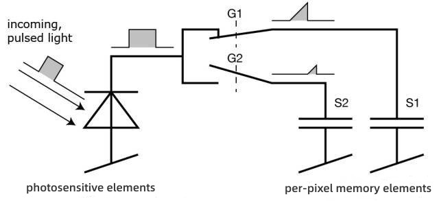
A control unit on the camera turns the light source on and off, sending out a pulse of light. At the same moment, the control unit opens and closes the electronic shutter on the chip. The charge S0 generated in this way by the light pulse is stored on the photosensitive element.
Then, the control unit switches the light source on and off a second time. This time the shutter opens later, at the point in time when the light source is turned off. The charge S1 now generated is also stored on the photosensitive element.
Because the duration of a single light pulse is so short, this process is repeated thousands of times until the exposure time is reached. The values in the light sensor are then read and the actual distance can be calculated from these values.
Note that the speed of light is c, tp is the duration of the light pulse, S0 represents the charge collected by the earlier shutter, and S1 represents the charge collected by the delayed shutter, then the distance d can be calculated by the following formula:
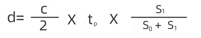
The smallest measurable distance is when all charge is collected in S0 during the earlier shutter period and no charge is collected in S1 during the delayed shutter period, ie S1 = 0. Substituting into the formula will give the minimum measurable distance d=0.
The largest measurable distance is where all charge is collected in S1 and no charge is collected at all in S0. The formula then yields d = 0.5 x c × tp. The maximum measurable distance is therefore determined by the light pulse width. For example, tp = 50 ns, substituting into the above formula, the maximum measurement distance d = 7.5m.
Hardware design and product features
Adopt the most advanced TOF hardware solution in the world; Class I safe laser, high pixel resolution, industrial-grade camera, small size, can be used for indoor and outdoor long-distance depth information collection.
Image processing algorithm
Using the world’s leading image processing and analysis algorithm, it has strong processing ability, takes up less CPU resources, has high accuracy and good compatibility.
Applications
Digital industrial cameras mainly used in factory automation, AGV navigation, space measurement, intelligent traffic and transportation (ITS), and medical and life sciences. Our area scan, line scan and network cameras are widely used in object position and orientation measurement, patient activity and status monitoring, face recognition, traffic monitoring, electronic and semiconductor inspection, people counting and queue measurement and other fields.
www.hampotech.com
fairy@hampotech.com
Post time: Mar-07-2023


